


Products
- Machines
- Workpiece
- Tools
Machines
LEARN MORE

14 Years Experience in Manufacturing and CNC Machines Supplier of Gear Hobbing Machines,Spiral Bevel Gear Machines,Gear Shaving Machine,Gear Grinding Chamfering Machine, Power Skiving Cutting Machines,CNC Machining Centers & Milling Machines,Spline Machines,CV …
Workpiece

Aim at providing perfect solution for each workpieces. Geepro high levels of automation coupled with machining quality guarantee productive manufacturing these workpieces.machining the following tooth parts: cylindrical spur gears, helical gears (shaft disk gears), worm small taper …
LEARN MORE
Tools
LEARN MORE
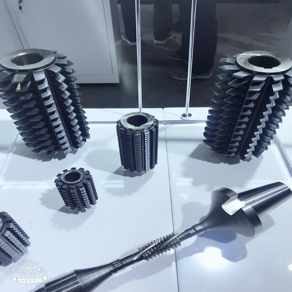
Gear Hobbing Tools, Milling cutter, turning gear cutter, hob cutter, gear shaper cutter, broach cutter, Cutting Blade, Workholding ,Progressive Press Molds Etc........

